Basics of Rotorcraft Design
The design of any aircraft starts out in three phases:
- Conceptual Design:
- The first design step, involves sketching a variety of possible aircraft configurations that meet the required design specifications.
- By drawing a set of configurations, designers seek to reach the design configuration that satisfactorily meets all requirements as well as go hand in hand with factors such as aerodynamics, propulsion, performance, structural systems, control systems and more.
- Preliminary Design:
- During this stage, the conceptual design is optimized to fit into the necessary parameters.
- In this phase, wind tunnel testing and computational fluid dynamic calculations of the flow field around the aircraft are done.
- Engineers will also look for structural defects and flaws, correcting them before proceeding to the third and final stage of the design process.
- Detailed Design:
- This phase simply deals with the fabrication aspect of the aircraft to be manufactured.
- It determines the number, design and location of ribs, spars, sections and other structural elements.
- Furthermore, all aerodynamic, structural, control and performance aspects are achieved and tested in full in the previous preliminary design stage.
- It may also include flight simulations to test the design and ensure it functions as intended.
HYDRA is an analysis tool which predominantly does the work belonging to Preliminary Design, but also covers some elements from the Detailed design. Once the mission statement and the rotor configuration are known, HYDRA determines the rotor parameters, namely rotor radius, RPM, wing span etc. It can also be used to obtain the spar materials, cross-section, airframe for a given vehicle.
Sizing
Empty weight and fuel weight fundamentally depend on total weight of the aircraft. Hence, iterative methods are needed for consistent vehicle design. Fixed-point iterations are performed to obtain a vehicle design. This requires mathematical models for each component. The inter-connected sizing loop is shown below:
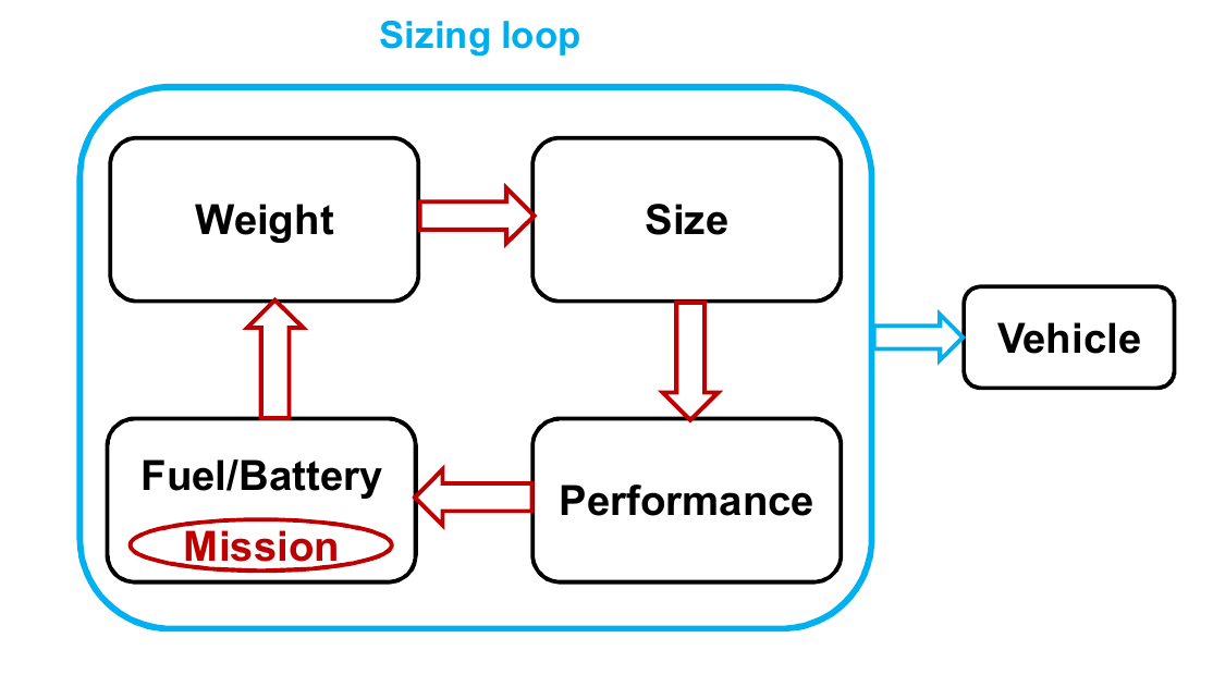
A brief understanding on the iterative procedure of the sizing loop shown above is given below:
- Sizing
- Estimatation of rotor dimensions from the input parameters.
- Example: Rotor radius from weight and disk loading, Blade chord from rotor solidity and number of blades.
- Power
- Compute the total required power of rotor and propeller using low-fidelity tools namely, BEMT or Momentum theory.
- Weight of Fuel
- With this information, compute the weight of the fuel/battery needed for the mission.
- Total Weight
- Given the vehicle size and performance, we estimate the total weight of the vehicle by accounting every weight group in the vehicle.
- The above iteration is repeated till the weight converges.
At the end of this sizing loop, the user will have the vehicle dimensions of the best possible configurations. A more detailed look at the various calculations that occur in preliminary sizing is given below.
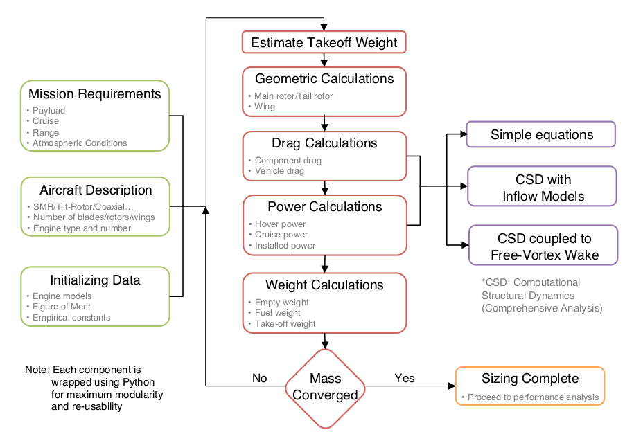
A short description on each of the tools used in HYDRA is given below. The intention of this short description is to make the user understand more technically. Interested users can refer to the links provided in the below sections, for more information on the respective topic.
Estimation of Weight
To estimate the weight of the components of vehicle, we resort to the following methods:
- Empirical Formulae
- Physics Based Models (FEA)
- Propulsion Banks
Empirical Formuale
A lot of design analysis is dependent on the empirical data. Some of the estimates of weight of vehicle components are obtained from the empirical data. For example, the weight estimation of fuselage for the helicopters is obtained as shown below:
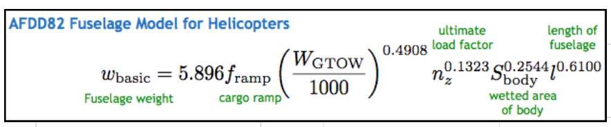
However, there are always some limitations when we use empirical models. The above weight model is valid for larger scale and not defined for lower weight scale.
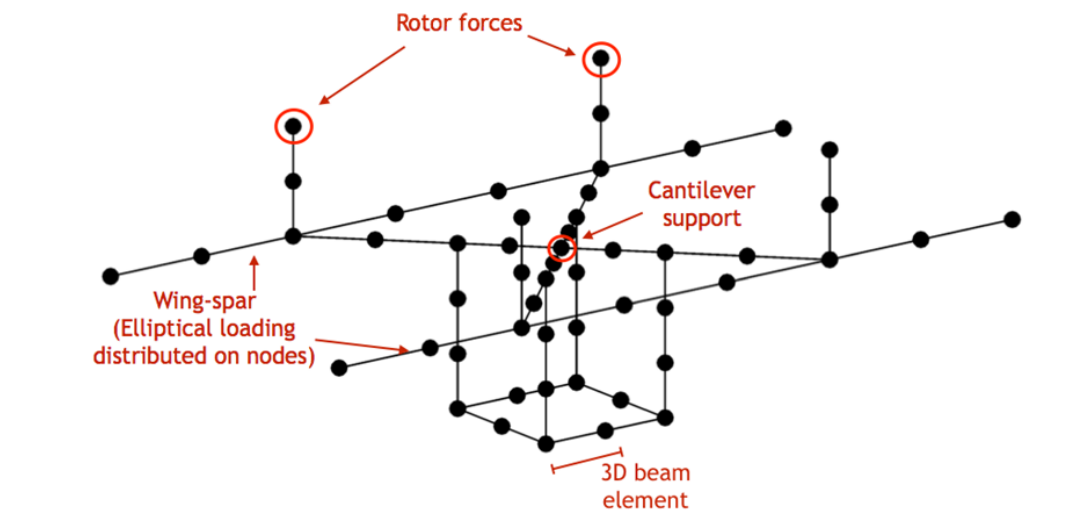
Physics Based Models (FEA)
For calculating the weights, HYDRA uses a finite element based static analysis with safety factors. Rotor loads and wing lift/drag are applied along at the rotor mounts and along the wing. As sizing proceeds, the model is sized up or down automatically based on rotor radius and wing span. A 3d beam lattice is used to define the load-carrying members, and the cross-sections are sized based on allowable stresses and deflections in hover and forward flight. Finally, the weight of the airframe members is used (with other components) to calculate the total empty weight, and subsequently the lift, drag and rotor thrust for sizing.
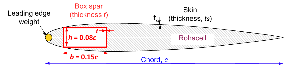
- The rotor blade weight is calculated
- neutral axis at quarter chord
- CG at quarter chord
- Spar: hollow rectangle
- Skin: uniform thickness
The above part has to explained properly…..some doubts need to be clarified…
Propulsion Banks
The weight of the engine is estimated from the data available. A trendline from the existing engine database is used to estimate the weight. An example for this is given by,
\(W_{engine}=-0.006594 P_{max}^2 + 1.828 P_{max} - 14.46\)
Need to add some more stuff here…..
Estimation of Power
The estimates for the power required for the mission are obtained using the existing mathematical models. Some of these, which are implemented in HYDRA, are mentioned below:
- Simple Equations (Momentum Theory)
- BEMT
- Comprehensive Analysis
- Free Wake
Simple Equations
This section deals with Momentum Theory…..
Blade Element Momentum Theory (BEMT)
Blade element momentum theory is a theory that combines both blade element theory and momentum theory. BEMT for prop-rotors with Reynolds/Mach tabulated airfoil properties is also available for use within the sizing loop. This feature reveals additional details of the rotor design, such as the best blade twist, taper, cruise RPM and root pitch travel. The additional fidelity weeds out infeasible rotor designs and also provides insight into the range of electric motor speeds or variable-speed transmissions required.
Comprehensive Analysis
Including Blade elastic deformations
Free Vortex Wake
Free Vortex problem……..It is computationally expensive.
Performance Analysis
Fuel, Weight Calculation
Fuel and weight calculation.